Taking into Account the Production Methodology and Estimating the Influence of Manufacturing Quality on NVH Performance when Sizing Gears
from GearTechnology.com author Dr. Ulrich Kissling, Founder of KISSsoft AG
Summary
Noise emissions from gear units in electric vehicles are a major problem. It is a well-known fact that if gears with high accuracy are used, their service life is increased and vibrations are reduced, improving the NVH (noise, vibration, and harshness) performance, resulting in less noise. For this reason, many EV (electric vehicle) manufacturers require a high to very high quality according to ISO 1328 (Ref. 8) for gear manufacturing.
In practice, the profile form deviation, in particular, is greatly restricted. In some cases, requirements are specified that are almost impossible to manufacture. This increases cycle times and therefore manufacturing costs. This begs the question whether the requested high quality actually produces any real improvements or whether, for example, a well-sized profile modification isn’t more effective than simply reducing the permitted manufacturing allowances.
For this reason, it would be sensible to find a method that can be used to estimate the influence of the manufacturing accuracy. When the gear profile measurement is analyzed, the signal is always statistically scattered and usually overlaid with a certain basic waviness. The size of this waviness directly influences the resulting profile form deviation.
This paper describes the basis for, and results from, a project that investigated the influence of quality on the resulting transmission error and the excitation force in the gear meshing. To achieve this, a sinus-shaped waviness is applied to the theoretical ideal tooth flank. The amplitude, length and initial value of the waviness can be modified. This modification can be applied in both the profile or flank line direction, individually, or both at the same time. The changes in transmission error, excitation force and other fundamental influences on the causes of vibration are then evaluated to obtain a result.
The amplitude or height of the waviness depends on the maximum permitted profile form deviation ffα, according to the selected quality. The waviness length or initial value can however vary during production, without any influence on ffα, depending on the situation. For this reason, it is necessary to take into account the result scatter for different forms of waviness. This can be achieved in an automatized process by combining different variants of amplitudes, lengths and phase angles, for the purposes of calculation. The changes in transmission error and other values that occur, can then be displayed and used to forecast the effect of the quality on the NVH performance. The application of this method to some current gear units is shown and discussed.
Considering the production methodology in the gear design process
Gear unit design and tooth flank modifications
When a gear unit is sized, a gear unit schematic is created, based on the requirements such as loads, speeds and output reductions. A schematic of this kind can then be modelled very efficiently in a drive systems software design package (Ref. 1)(Figure 1). The dimensions of gears, shafts and bearings can be defined with sizing functions. This very quickly provides the designer with an initial draft that already meets fundamental requirements such as minimum safeties and/or service life.
After adjustment of the gearbox dimensions to given spatial boundaries and other constraints, static and dynamic simulation of the gearbox is performed. This enables the specialist to identify which tooth flank modifications are necessary to avoid tooth damage due to deformation under load. Nowadays, profile and flank line modifications specifically intended to minimize excitations of vibration (noise!) or losses (efficiency!) are extremely important. Tooth modifications of this kind are made for reasons of purely functional nature. Most often such modifications are crownings in the profile and flank line direction.
Tooth flank modifications that have been defined for purely functional reasons can usually only be manufactured approximately. It is then the task of the manufacturing department to achieve this function-oriented tooth modification as accurately as possible.
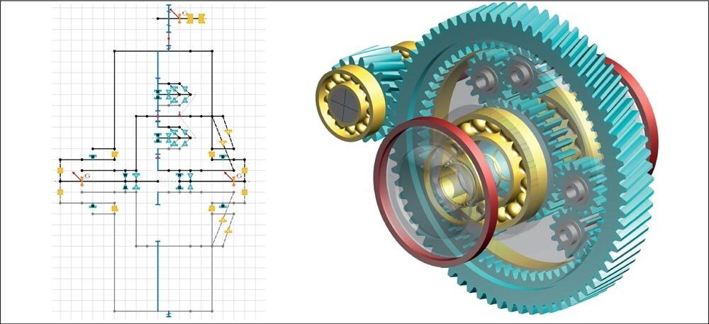
Figure 1—Gearbox design of a lightweight differential, for an EV. Left: Gear unit schematic representation in the KISSdesign® Sketcher. Right: View of the 3D model after pre-sizing in KISSdesign® (Ref. 1).
Gear manufacture methods
A multitude of different processes for manufacturing cylindrical gears are available (Figure 2). For pre-machining, processes such as hobbing, profile milling, shaping, broaching or skiving are available. Fewer processes exist for hard finishing, mainly generation grinding, profile grinding and gear honing. Gears are produced based on the tool geometry and process kinematics. The kinematic is calculated by the control software of the machine, using the theoretical gear data and the required tooth modifications.
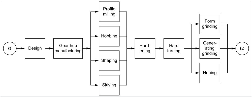
Figure 2—Customary production process for cylindrical gear manufacture.
Usually, the design department designs a gear with little discussion about the production. If the production is outsourced, as is often the case nowadays, during the design phase usually no decision is taken as to who will produce the gears, or which process will be used.
Taking the production methodology into consideration during the design process
Every production method (Figure 2) has its own specific properties that either enable the method to produce a particular tooth modification well, reasonably well or not at all. The machine operator in the production is faced with the problem of producing a modification that cannot be created mathematically exact. Consequently, the required modifications are produced with an approximation which is more or less good. If the operator then succeeds in creating the gear within the specified tolerance, he is happy with that. Deviations from the required modifications are checked during production with profile and flank line measurements. This process is of limited use for checking topological modifications. A reasonable tolerance interval is necessary for gear production, otherwise the production costs may become excessive. The question remains, if a gear produced inside the given tolerances will have the gear properties intended by the designer.
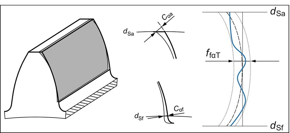
Figure 3—Determination of a profile form deviation ffα.
For example, a profile form deviation is defined in such a way that the required profile form, shown as a dashed line in Figure 3, is moved as far to the right and left (shown as pointed lines) as is necessary to touch the measured profile form, shown as a thick blue line. The distance by which the profile form is displaced to the left and right then accounts for the profile form error ffα according to ISO 1328. It is obvious that there are different profile forms that all have the same value for ffα. This methodology can only partially evaluate the influence that a specific deviation of this kind has on a gear’s noise characteristics. The same applies for the flank line form deviation (Ref. 3).
Example: Natural twist resulting from flank line crowning
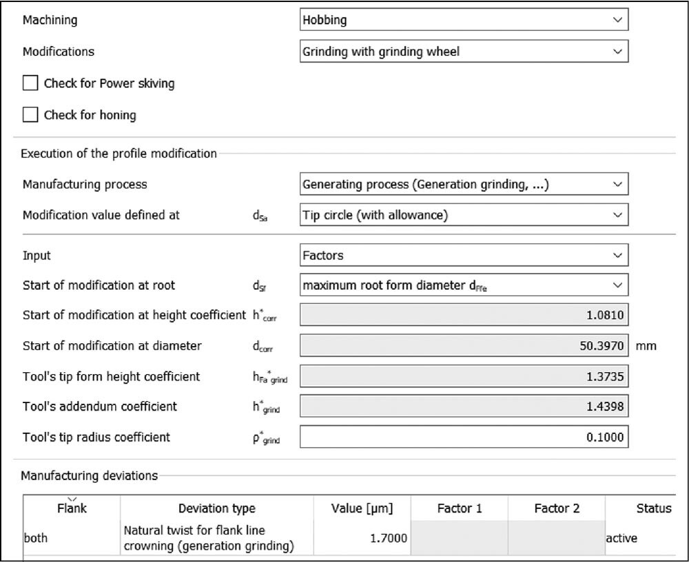
A classic example, how the manufacturing process can influence the tooth properties, is the production of flank line crowning on a simpler grinding machine. During the generation grinding process of a helical gear tooth, the movement of the tool results in a specific deviation error called “natural twist.” This deviation consists of a twist with a small overlaid profile crowning (Figure 4). Modern grinding machines can compensate for this twist caused by manufacturing, but simpler machines cannot. Such a twist can greatly influence the contact pattern and the excitation characteristics in the meshing and is normally not desirable.
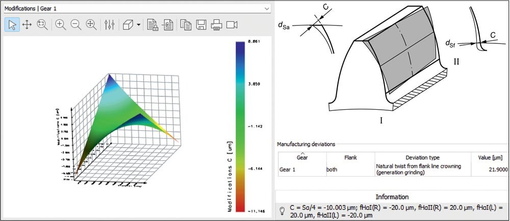
Figure 4—Natural twist caused by manufacturing (Sα 10,004 μm according to ISO 21771) when a flank line crowning (21.9 μm) is produced using generation grinding. Calculation in KISSsoft® (Ref. 1).
However, in the case of a helical gear, a flank twist is sometimes deliberately used as a modification, in certain cases. This shows that a twist caused by manufacturing can sometimes be useful. If the design software enables the twist caused by manufacturing to be calculated and taken into account in the contact analysis, the resulting manufacturing deviation can be included at gear sizing stage. This simplifies the grinding process considerably and it is easier to achieve the target contour.
Please, continue reading at
https://www.geartechnology.com/articles/30093-taking-into-account-the-production-methodology-and-estimating-the-influence-of-manufacturing-quality-on-nvh-performance-when-sizing-gears
or contact Us for more information and consultation regarding the topic.
*KISSsoft is a registered trademark of KISSsoft AG
 Dubai
Dubai